
The primary load on the CAP is the bias current of the LMC555 timer chip. The voltage at C4 is connected to pin 10 of IC 1/3 lower than pin 9, Makes pin 8 no voltage out. The C4 will be out of the R9 discharge for about 1 minute. Note that the sloping down high level of the output pulse is caused by the sag of the voltage on C1. The Q1 is pull the voltage at pin 9 through D5, R13, so cause pin 9 of IC1/3 has a lower voltage. In order to obtain time delay, we are using 555 timer IC for this purpose. A time delay circuit can be useful for any circuit that needs a delay before output turns on.

The main principle of this circuit is to generate a pulse signal after some time delay.
Simple delay timer latch circuit how to#
The following picture shows the waveform behavior that you can expect from this circuit. In this tutorial, we will show you how to make a Time Delay Circuit using 555 Timer IC. The size of the hold up capacitor may have to increase if there is a load placed on the output pin with the 5 second high pulse. In this circuit the hold up capacitor is the 220uF part at C1. An SCR (Silicon Controlled Rectifier) is a controllable medium- to high-power self-latching. (Do not use the old standard NE555 type part. Basic operation and practical application circuits for SCRs. Here is a sample circuit that would do the job using the CMOS version of the 555 chip. The timing of 5 seconds could be implemented via an R/C circuit, a timer IC or a small pin count microcontroller.

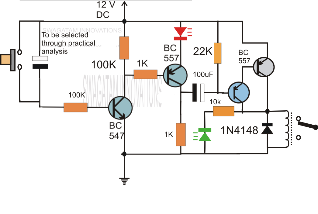
And to calculate the component values for a given delay time, it is easier to fix the value of capacitor and calculate the resistor value. Short explanation for the circuit: My SW1 is just me giving one 5V pulse to the circuit. b) would like to understand, why the time delay gets that high (and also, why its getting higher, the longer its functioning without a reset (up to 15seconds)). It somehow does what I want, but I would like to. The captured state enables the five second time delay which when it expires will feedback and clear the capture latch. For example, in the circuit diagram of the fixed delay duration timer, we have used a 68K resistor and 470uF capacitor which gives us a delay time of: T 1.1 (68000) (0.000470) 32 seconds. I am trying to use the following circuit. Variable resistor R1 can be adjusted to get different time delays. When the trigger pulse arrives it clocks a state to the circuit that is powered from the capacitor power. The IC4060 is a 14- stage binary ripple counter which generates the basic time delay pulses. The 1K and the 1N4148 link makes sure that whenever the transistors work out the latch on account of inadequate charge in the capacitor, the residual charge inside the capacitor is. Your solution will need to be based upon a capacitor that stores energy to be used by the output circuit to hold up high level pulse. In spite of this the addition of the 1K/1N4148 network immediately the transforms the circuit into a greatly precise long duration timer for the following factors.


 0 kommentar(er)
